Renumber Points FIRST!
Renumber all existing points first to avoid problems (Add 5000 or 10000 to the existing Point Numbers)
Check Styles & Settings are Imported...
Ensure ‘ONK XXX’ Point Styles are imported from Template
Ensure ‘ONK_XXX’ Label Styles are imported from Template
Ensure all ‘Setout XXX’ Point Groups are pasted from Template (Dragged & Dropped)
Ensure ‘ONK’ Description Key Set is imported from Template (Dragged & Dropped)
(Note: All of the required Styles & Settings are included in the new Template, If in doubt, re-import)
Points are not dynamically linked to the Corridor or Surface
The Setout Points you create will be COGO Points but they will not be dynamically linked to the Corridor or Surface, if your Corridor design changes or your Surface changes you will need to re-create the Offset Feature Line or update the COGO Points elevations from Surface.
Use of Point Codes
Points will be Created and Placed in Point Groups depending on the Point Code entered…
(Ie. Points using Point Code EB will be placed in 'Setout EP' Point Group and 'EDGE BITUMEN' will be used in the Table Description)
Available Point Codes...
(Others can be created within the Description Key Set if required)
EB = Edge Bitumen
EP = Edge Path
LIP = Kerb Lip
LM = Linemarking
LP = Light Pole
RSB = Road Safety Barrier
SP = Spot Level
SW = Drainage Pit
WT = Kerb Water Table
OPTION A (For Setout Points from Corridors)
Setout Points using Offset Feature Lines
Set Frequency of Corridor Regions to correspond with desired Setout PointsIsolate required Corridor and/or Feature Lines to create Setout Points
Click on the Corridor on the line you wish to create Points along (Ie. Flowline_Gutter)
Using the Ribbon select ‘Feature Lines from Corridor’
(Note: Ensure that the Smoothing and Dynamic Link to Corridor boxes are Unchecked)
An 'Automatic Feature Line' will be created
(Note: The above step ensures that all Frequencies are transferred across to Offset Feature Line as Vertices)
Offset the Feature Line the desired Offset Width using the AutoCad ‘Offset’ command (Typically 1.5m)
Explode the Feature Line, which will become a 3D Polyline and put on the required layer, typically ‘SETOUT’
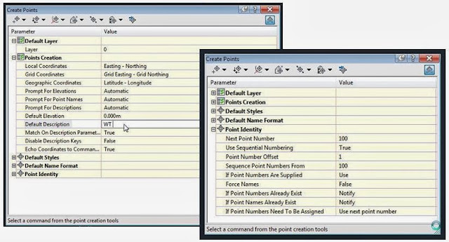
Go to Points> ‘Create Points…’ and check all the Settings are as below…
(Note: Point Labels & Styles are set automatically using the Description Key Set)
Set the Default Description that you require, based on the Setout Point required (Ie. SW, EB, WT etc.)
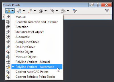
Use the 'Polyline Vertices - Automatic' command to create Setout Points along the 3D Polyline
Use the 'Polyline Vertices - Automatic' command to create Setout Points along the 3D Polyline
Your Setout Points will now be created, if required Regen your view to show Points
(Note: The Next Point Number option doesn’t always work… Therefore Renumber as required)
OPTION B (For Setout Points from Gradings)
Setout Points using Feature Lines
Offset the Feature Line the desired Offset Width using the AutoCad ‘Offset’ command (Typically 1.5m)Go to Points> ‘Create Points…’ and check all the Settings are as below…
(Note: Point Labels & Styles are set automatically using the Description Key Set)
Set the Default Description that you require, based on the Setout Point required (Ie. SW, EB, WT etc.)
Use the 'Measure Object' or 'Divide Object' command to create Setout Points along the Feature Line
Explode the Feature Line and put on the required layer, typically ‘SETOUT’Use the 'Measure Object' or 'Divide Object' command to create Setout Points along the Feature Line
Your Setout Points will now be created, if required Regen your view to show Points
(Note: The Next Point Number option doesn’t always work… Therefore Renumber as required)
OPTION C (For Setout Points from Corridors)
Setout Points using 'LinkWidthAndSlope' Subassembly
Add a Generic Subassembly ‘LinkWidthAndSlope’ to your Subassembly(s) as required
- Width = The desired Offset Width (Typically 1.5m)
- Slope = 0.00%
- Point Codes = The desired Setout Point Code (See below)…
- Omit Link = ‘Yes’
Right Click the Corridor and select ‘Rebuild Corridor…
Once Points are Created, Go to the Home>Points>’Create COGO Points from Corridor’
Select the desired Range
Set the desired Point Group Name
‘Shift Select’ all of the Codes, uncheck and select only the required Codes
Once created, the created Points will be placed in their corresponding Point Groups by Code. You can then manipulate as required for your project and create new groups if required.
(Note: Point Labels & Styles are set automatically using the Description Key Set)
(Note: To ensure that Section Views display correctly you will need to do the following...) Right Click the Corridor and select ‘Corridor Surfaces…’
Go to the ‘Boundaries’ Tab
Remove the Corridor Shrinkwrap (Corridor Extents as Outer Boundary) if you have one…Right Click the Corridor and select ‘Add Automatically’
Select the Code that you want to use to create your Corridor Surface Boundary. The other ‘Add’ options can be used as required…
ADDITIONAL FUNCTIONS
Add Extra Points to Alignment (Station/Offset)Use the ‘Station/Offset’ command within the ‘Create Points’ command to Create Point(s)
Select the Required Profile (Typically the Design Profile)Specify the Station by Clicking On-Screen
Specify the Offset at the Command Prompt
Add Extra Points to Alignment (Manual)
Use the ‘Manual’ command within the ‘Create Points’ command to Create Point(s)Specify the Point Location by Clicking On-Screen
Renumber Points
Where Points are in Sequence (1,2,3,4,5,6… etc.)
Renumber Points
Where Points are Random (Ie. 1,5,6,7,10… etc.)
Type “APPLOAD” at the Command PromptWhere Points are Random (Ie. 1,5,6,7,10… etc.)
Follow the prompts to load L:\DESIGN>DESIGN SUPPORT>ACAD Support>ACAD Lisp files>RENUM
Type “REORDERPOINTS” at the Command Prompt
Follow the On Screen Prompts;
- Select a Starting Number (Enter a number Higher that the last used Point Number)
- Use the ‘Fence’ Selection Type (Draw the fence through the points in Desired Order)
- Follow Prompts to finish
(Note: The Points may take a while to appear… Using ‘Refresh’ or ‘Update’ may help…)
Navigate to the Prospector>Point Groups> ‘Desired Point Group’. Then Right Click ‘Edit Points…’ Click in the ‘Point Number’ Column and press ‘Ctrl+A’ to Select All. Then Right Click ‘Renumber…’ within the Highlighted column area. In the Command Prompt you will be asked for an “additive factor for point numbers” Enter the number you wish to add to the Points. (Ie.To change numbers 33-45 to 100-112 Enter [67]. To change numbers 33-45 to 10-22 Enter [-23]).
Create Setout Tables within Civil 3D
Use the Points> ‘Add Tables…’ command
Select the desired Style. Ie. ‘ONK Setout - Civil - 1.5m Offset
Ensure the Layer is set to ‘C-TABLES_Text’
Select the Desired Point Group or Select Points On Screen
Uncheck ‘Split Table’ Option (Unless you want to Split the Table…)
Leave the ‘Behaviour’ as ‘Dynamic’
Check ‘Sort Data’ Checkbox
(Note: Please check Offsets and Descriptions to ensure they are as expected)
To Edit Offsets, Right Click on Table and Select ‘Edit Table Styles…’ command (Only 1 Offset Width can be used by this method unless the ‘Explode’ command is used and various Offsets entered manually).
To Edit the Descriptions, navigate to the Prospector>Point Groups> ‘Desired Point Group’. Then Right Click ‘Edit Points…’ Click in the ‘Raw Description’ Column and press ‘Ctrl+A’ to Select All. Then Right Click ‘Edit…’ within the Column Heading.
Create Setout Tables via Microsoft Excel
Navigate to the Prospector>Point Groups> ‘Desired Point Group’. Then Right Click ‘Edit Points…’ Click in the ‘Point Number’ Column and press ‘Ctrl+A’ to Select All. Then Right Click ‘Export…’ within the Highlighted column area.(Note: Ensure that the ‘Destination File’ is saved in ‘.Csv’ format)
Open the Exported File and Copy and Paste Cells into the Setout Table located in the ‘References’ Folder.
Paste the Data using the ‘Values (V)’ option to retain formatting (from the Right Click>Paste)
Add and Edit the ‘Description’ and ‘Offset’ information as required
Copy and Paste the Tables into Layout (Paperspace) in Civil 3D
Multiple Offsets in the one Setout Table
If you want to have multiple Offsets within the one Setout Table this can be achieved by using the 'Setout Offset' Parameter of a Point. (Note: I have already created this User-Defined Property Classification within our Template). To create this Parameter from scratch refer to the following post User-Defined Property Classifications for Points.
Our Points Tables use a pre-defined Setout Offset (Ie. 1.5m) which exists in the Table Style. To use the 'Setout Offset' Parameter you will need to set the desired offset for each point that will be used in your Setout Table. You will find this Parameter in your Point Properties dialog box or Point Editor.
Once you have assigned the 'Setout Offset' Parameter to all of the required points you can edit the Table Style.
Right Click the Table and select ‘Edit Table Style…'
Double Click the 'OFFSET' Column 'Column Value'
You will then need to change the 'Properties' in the 'Text Component Editor' from the pre-defined value (Ie. 1.5m) to use the 'Setout Offset' Parameter. (See below...)

You should now find that your Setout Table shows the multiple Offsets correctly.


This comment has been removed by the author.
ReplyDeleteThere is no such thing as a 'Polyline Vertices - Automatic' command
ReplyDeleteHi, You are correct, it is a Points Creation Method that you can use within the 'Create Points' command. Regards.
ReplyDelete